Table of Contents >> Show >> Hide
- Why This Combination Is So Popular
- What the 74HC595 Actually Does
- Understand the 7-Segment Display Before Wiring Anything
- Basic Wiring for One Digit
- How the Data Flow Works
- Simple Arduino-Style Example
- Driving More Than One Digit
- Common Problems and How to Fix Them
- Practical Experiences With the 74HC595 and 7-Segment Displays
- Final Thoughts
If you have ever built a project that needed a numeric display, you have probably run into a classic tiny disaster: your microcontroller runs out of pins faster than your patience runs out of coffee. That is exactly why the 74HC595 shift register remains a favorite in hobby electronics, student builds, and quick prototypes. It lets you trade a pile of parallel control lines for a small set of serial signals, which means you can drive LEDs and 7-segment displays without turning your breadboard into a spaghetti museum.
Pairing a 74HC595 with a 7-segment display is one of those projects that looks simple on paper and then humbly reminds you that polarity, resistor placement, and bit order still matter. A lot. The good news is that once you understand the logic, this setup becomes wonderfully reusable. You can display digits, countdowns, error codes, temperatures, timer values, and simple status information with very little hardware.
In this guide, we will walk through how the 74HC595 works, how 7-segment displays are wired, what changes between common-anode and common-cathode models, how to shift digit data into the chip, and what to watch for when you move from one digit to several. By the end, you should have a clear, practical understanding of how to use the 74HC595 shift register to drive 7-segment displays without sacrificing your last usable GPIO pin or your sanity.
Why This Combination Is So Popular
The appeal is easy to understand. A single 7-segment display uses seven LEDs for the numeral itself and often one more for the decimal point. If you drive that directly, you can burn through eight microcontroller pins for one digit alone. Add more digits, and your pin budget starts filing a formal complaint.
The 74HC595 solves that by acting as a serial-in, parallel-out device. You send data one bit at a time from the microcontroller, and the chip presents those bits across eight outputs. That means only a few control lines are needed from the microcontroller, while the display still gets its parallel segment signals.
For simple one-digit projects, the 74HC595 is a clean and inexpensive way to drive the display. For multi-digit builds, it is often used with cascading or multiplexing so you can expand the display without expanding your GPIO demands at the same rate. That is why you see this part in clocks, counters, timers, basic instruments, and beginner Arduino projects everywhere.
What the 74HC595 Actually Does
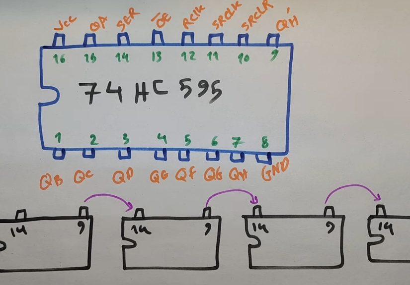
The 74HC595 is an 8-bit shift register with a storage register and tri-state outputs. That sounds like textbook language, but the practical meaning is much friendlier. Think of it as an 8-bit holding tray for on/off values. You feed bits into the chip one at a time, clock them through, and then latch them so the outputs update together.
The Three Main Control Lines
Most basic projects use three microcontroller signals:
- Data sends the 1s and 0s into the chip.
- Shift clock moves each incoming bit through the register.
- Latch clock copies the shifted data to the output pins all at once.
That last part matters. If you updated outputs one bit at a time, your display would briefly show garbage while new data moved in. The latch keeps the old pattern visible until the new one is fully loaded, then flips the whole byte to the outputs in one move. Very neat. Very civilized.
Other Pins You Should Not Ignore
The 74HC595 also includes an OE pin, which is output enable, and an SRCLR pin, which clears the shift register. OE is active low, so tying it low enables the outputs. If you connect OE to a PWM-capable pin, you can dim the whole display by modulating the output enable line. SRCLR is also active low and is usually tied high in simple designs so the register is not constantly cleared.
The QH’ serial output pin is what makes cascading possible. Connect that pin to the data input of the next 74HC595, and now one byte becomes two, then three, then however many your project needs.
Important note: the 74HC595 is great for expanding logic outputs, but it is not a brute-force LED driver. For bright displays, higher current, or multi-digit designs, you may need transistor stages or a dedicated display driver IC.
Understand the 7-Segment Display Before Wiring Anything
A 7-segment display is simply a package of LEDs arranged as segments labeled a through g, plus an optional decimal point. The catch is that those internal LEDs can be wired in one of two common ways: common cathode or common anode. If you mix them up, your code will look guilty even when the real culprit is the hardware.
Common Cathode
In a common-cathode display, the shared pins connect to ground. A segment lights when its individual pin is driven high. This feels intuitive because a logic HIGH turns a segment on.
Common Anode
In a common-anode display, the shared pins connect to VCC. A segment lights when its individual pin is driven low. In other words, the logic is inverted. Your segment pattern for a numeral still exists, but the bits must be flipped compared with a common-cathode design.
Use One Resistor Per Segment
This is the part beginners love to skip right before the circuit teaches them a life lesson. Each segment should have its own current-limiting resistor. One resistor for the whole display might look clever, but it creates uneven current sharing and unpredictable brightness because different numbers light different combinations of segments. Separate resistors keep the current under control and the display behavior much more consistent.
Basic Wiring for One Digit
For a single-digit setup, the wiring is fairly direct. A typical arrangement looks like this:
- Microcontroller data pin to SER on the 74HC595
- Microcontroller clock pin to SRCLK
- Microcontroller latch pin to RCLK
- OE tied low
- SRCLR tied high
- 74HC595 outputs QA-QH to segments a-g and decimal point through resistors
- Display common pin to GND for common cathode, or to VCC for common anode
If you are using a common-cathode display, driving an output high will usually light that segment. If you are using common anode, driving the output low will light it instead. Same hardware family, very different attitude.
Resistor values commonly land in the 220 to 470 ohm range for many 5 V hobby projects, but the correct value depends on supply voltage, LED forward voltage, target brightness, and the current you want each segment to draw. Always size the resistor based on the actual display and current budget, not on ancient breadboard folklore.
How the Data Flow Works
To display a number, you need a byte pattern representing which segments should be lit. For example, the digit 0 lights segments a, b, c, d, e, and f, but not g. The digit 1 lights only b and c. That pattern is packed into a byte and shifted into the 74HC595.
- Pull the latch line low.
- Shift out the byte for the desired digit.
- Pulse the latch line high.
- The display updates to the new numeral.
The exact bit pattern depends on your segment wiring order. Some projects wire Q0 to segment a, others start somewhere else, and code examples may use gfedcba, abcdefg, or include the decimal point in bit 7. That is why copied code sometimes “works” by displaying a mysterious sideways 2 that seems emotionally unavailable. The code is not always wrong; it may just assume a different wiring map.
Simple Arduino-Style Example
Here is a compact example for a common-cathode display, assuming your wiring matches the bit order used by the table. If your display is common anode, invert the byte values or build a separate lookup table.
The key phrase there is adjust bit order to match your wiring. If your segments do not line up with the lookup table, the display will not show the expected numeral. Build a quick segment test routine first if you want to save yourself later confusion.
Driving More Than One Digit
One digit is easy. Multiple digits are where the project becomes more interesting and slightly more dramatic. There are two common ways to expand:
1. Cascade More 74HC595 Chips
You can chain multiple shift registers by feeding the serial output of one into the serial input of the next. This gives you more output bits with the same core control lines. For multiple static outputs, that is wonderfully efficient.
2. Multiplex the Display
Multiplexing is the usual method for multi-digit 7-segment displays. All like-named segments are tied together across the digits, and each digit gets its own enable line. Then the system rapidly turns on one digit at a time while outputting the segment pattern for that digit. Do it fast enough, and human vision blends the scan into a stable display.
This approach saves a lot of pins, but it introduces design trade-offs. Refresh timing matters. Brightness can drop because each digit is only on for part of the cycle. And the current demands often become high enough that transistors are the smarter choice for digit enables or segment driving.
When You Should Add Transistors or Use a Driver IC
If your display is dim, if multiple segments need more current than the chip should comfortably handle, or if you are building a larger multi-digit module, do not force the 74HC595 to become something it is not. Add transistor drivers, use a transistor array, or consider a dedicated LED driver. The 74HC595 is excellent for control logic, but it should not be volunteered for weightlifting without backup.
Common Problems and How to Fix Them
The Wrong Number Appears
Your segment lookup table probably does not match the actual wiring order. Test each segment one by one and rebuild the table.
Nothing Lights Up
Check OE and SRCLR first. OE must be low to enable outputs, and SRCLR must not be held low unless you want the register cleared.
Everything Is Backward
You likely wrote code for a common-cathode display but wired a common-anode module, or the other way around. Invert the logic.
Brightness Is Uneven
That can come from missing per-segment resistors, poor multiplex timing, or trying to drive too much current through the chip.
The Display Flickers
Your multiplex refresh is too slow, or your update routine is spending too much time elsewhere. Tighten the scan loop.
The Breadboard Works, the PCB Does Not
Double-check the pinout of the actual display part number. Two displays may look almost identical while having different common-pin arrangements. Electronics can be polite right until they are not.
Practical Experiences With the 74HC595 and 7-Segment Displays
Anyone who spends real bench time with the 74HC595 and a 7-segment display usually goes through the same set of experiences. The first one is optimism. You look at the chip, count three control wires, and think, “Amazing, I have defeated pin shortage forever.” Then the second experience arrives: the display lights up, but it shows something that looks less like an 8 and more like a digital cry for help. That moment usually teaches the most important lesson of the whole project, which is that segment order matters just as much as the code.
Another common experience is discovering that common anode and common cathode are not tiny labeling details. They are personality types. A builder can spend half an hour debugging software before realizing the hardware needs inverted logic. Once that clicks, the entire project suddenly behaves, and the relief feels wildly disproportionate to the size of the chip involved.
People also learn very quickly why separate resistors are worth the extra parts. When a beginner uses one resistor for the whole display, some digits look acceptable, others look odd, and brightness seems to change depending on how many segments are on. It feels mysterious until you understand that different numerals place different current demands on the circuit. After that, one resistor per segment stops feeling fussy and starts feeling like common sense.
Then there is the experience of moving from one digit to four. On paper, multiplexing looks elegant. In practice, it teaches timing, current limits, and the value of writing code that does one thing consistently and quickly. Builders often discover that a multi-digit display can look dim or flickery if the refresh loop is too slow or if too much processing happens between digit updates. The fix is rarely magic. It is usually cleaner timing, better current management, and sometimes admitting that a transistor or dedicated driver belongs in the design.
There is also a very specific kind of satisfaction that comes from the first time a multiplexed display works properly. The digits appear stable, the count is correct, and the whole project suddenly feels more “real.” What started as a handful of wires becomes a timer, a counter, a clock, or a readout that looks like it belongs in an actual device rather than a science-fair panic station.
One more practical lesson shows up in code reuse. Once you build a good lookup table, a segment test routine, and a reliable shift-and-latch function, you stop reinventing everything for each project. The 74HC595 becomes a dependable building block. That is probably the biggest real-world advantage of learning it well. The chip is cheap, flexible, and widely understood, so the effort you put into one 7-segment project pays you back on the next one, and the one after that.
In the end, the experience of using the 74HC595 to drive 7-segment displays is less about one particular chip and more about learning a core embedded-systems habit: respect the relationship between hardware wiring, current limits, and software logic. Once you get that trio working together, the project stops feeling fragile and starts feeling engineered.
Final Thoughts
Using the 74HC595 shift register to drive 7-segment displays is one of the best small projects for learning how digital control, wiring discipline, and display logic fit together. It saves GPIO pins, scales well, and teaches practical lessons that carry into bigger embedded designs. For a single digit, it is simple and clean. For multiple digits, it opens the door to cascading and multiplexing. And for anyone learning electronics, it provides exactly the right mix of “Hey, this is clever” and “Ah, that is why the resistor goes there.”
If you match the code to the wiring, choose the correct display type, size the resistors properly, and respect the current limits of the chip, the 74HC595 becomes a reliable little workhorse. Not flashy. Not trendy. Just extremely useful, which in electronics is often the highest compliment possible.